These material checks are common to many different connection types.
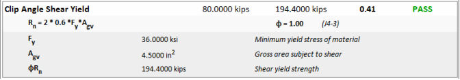
Shear yielding occurs over the gross cross section of elements in shear, such as shear tabs. The shear yielding capacity is calculated per the AISC 360-10 specification, section J4.2.
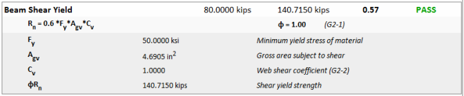
A special case occurs when considering the beam web shear yielding. In this case the shear yielding capacity is calculated per the AISC 360-10 specification, section G2.1. The capacity is calculated per equation G2-1 and the Cv values are calculated using G2-2, G2-3, G2-4 and G2-5.
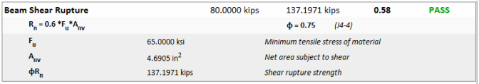
Shear rupture occurs over the net cross section of elements in shear, such as shear tabs. The shear rupture capacity is calculated per the AISC 360-10 specification, section J4.2.
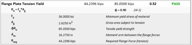
Tensile yielding occurs over the gross cross section of elements in tension such as flange plates in a moment connection or even the beam itself. The tensile yielding capacity is calculated per the AISC Specification J4.1.
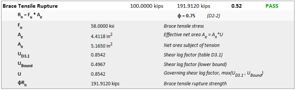
Tensile yielding occurs over the gross cross section of elements in tension such as flange plates in a moment connection or even the beam itself. This effective area is taken as the minimum of the net area, or 85% of the gross area. The tensile rupture capacity is calculated per the AISC Specification J4.1.
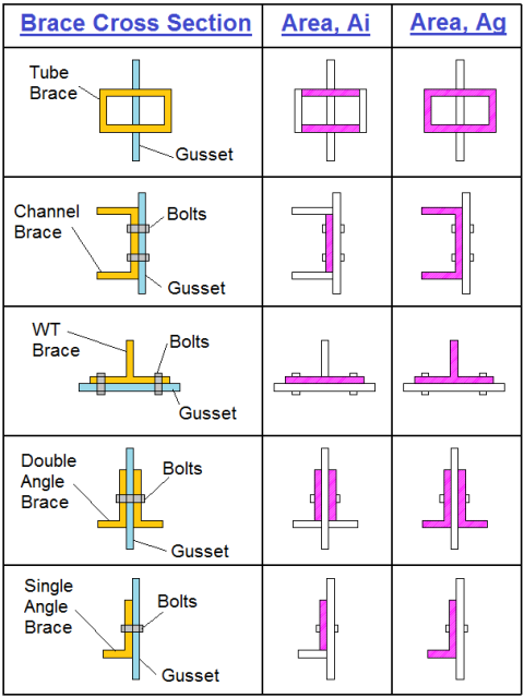
For the braces in vertical brace connections a shear lag factor is included per the AISC 360-10 specification, Section D3.
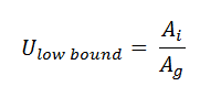
The program also checks the shear lag lower bound factor per the Commentary to section D3 on page 16.1-284. This section allows the "ratio of the area of the connected element to the gross area" as a reasonable lower bound value.
The gross area is the full cross-sectional area (ignoring the bolt holes). The net area removes the area of bolt holes from the gross area. This is done per AISC 360-10 section B4.3b which says that "the width of a bolt hole shall be taken as 1/16 in greater than the nominal dimension of the hole."
For Flange Plate Moment Connections, the nominal flexural strength of the beam is checked per AISC 360 equation F13-1.
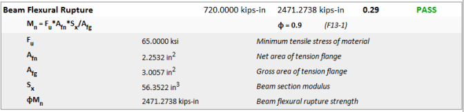
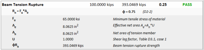
To compliment the Beam Flexural Rupture check (see above) for Flange Plate Moment Connections, the Beam Tension Rupture limit state will also be checked per AISC 360 equation D2-2 when there is an axial tensile force present. This check does not apply for zero axial or compressive loads.
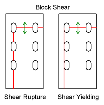
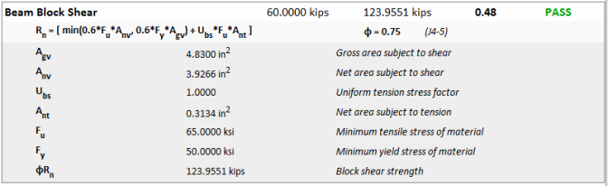
Block shear is a combination of tensile rupture, and either shear yielding or shear rupture. The program checks both types of block shear per the AISC 360-10 specification, section J4.3.
Note:
Block shear is not likely to control for beam webs unless the beam is coped. However, RISAConnection does check this failure state for completeness. The area of the beam flange directly above the web on either side will yield or rupture with the web. In the image below, for example, the orange area of the web represents shear yielding or rupture of the web area. The red shading is the area of the flange (one on each side of the web) that must also fail for the block shear limit state to occur.
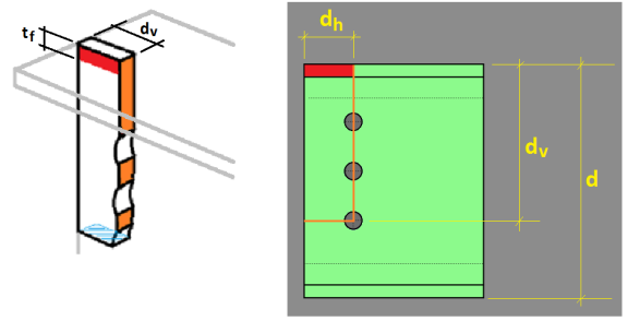
This failure mode is calculated as block shear using an "inside" perimeter rather than an "outside" perimeter.
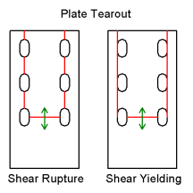
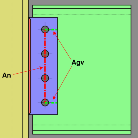
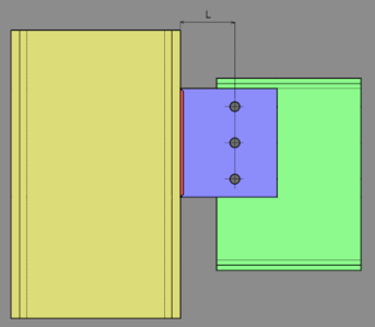
The Net Area Subject to Tension (An) and Gross Area Subject to Shear (Agv) used to calculate plate tearout is shown in the figure below.
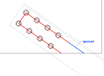
On gusset plates where the free edge of the tearout portion is not perpendicular to the direction of force an effective shear area is used. This program ignores the minimum amount of shear area necessary in order to produce a symmetric tearout pattern. See the dialog below.
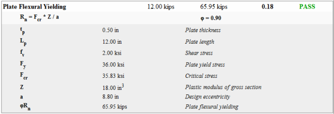
Flexural yielding occurs in elements of shear connections which take moment due to eccentricity. This effect is negligible, and is therefore ignored for clip angles and end plates. This effect also does not affect moment connections, since eccentricity may be ignored. The program does check flexural yielding for shear tabs, as it can be a controlling failure mode for extended configurations.
This check is not required if all of the following conditions are met:
For more information, see the AISC 13th Edition Manual, page 10-101.
The design check for flexural yielding is outlined in the AISC 13th Edition Manual, page 10-103.
Note:
Per the specifications in the AISC design code, shear splices are designed for the following:
Please see page 10-139 of the AISC 14th edition (pg 10-129 of the AISC 13th edition) for more information.
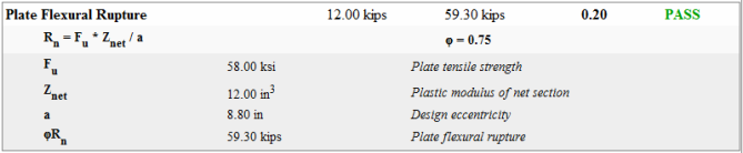
Flexural rupture is a check exclusive to extended shear tab connections. For more information see Flexural Yielding, and the AISC 14th Edition Manual, page 9-6.
Per the specifications in the AISC design code, shear splices are designed for the following:
Please see page 10-139 of the AISC 14th edition (pg 10-129 of the AISC 13th edition) for more information.
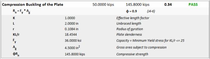
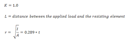
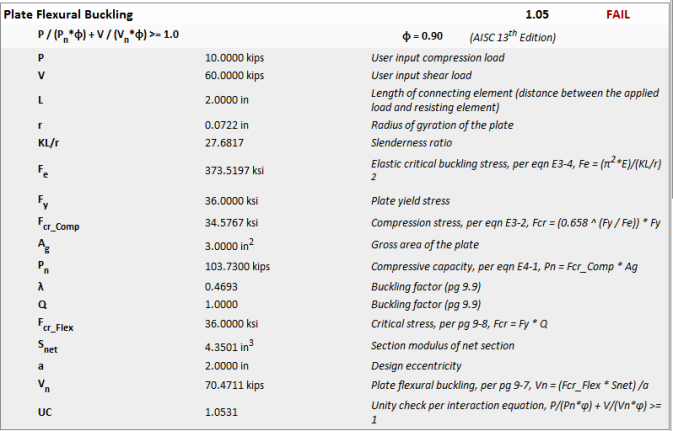
Compression yielding occurs over the gross cross section of elements in compression such as the shear plate or clip angle under compressive axial loads. The compression buckling capacity is calculated per the AISC Specification J4.4.
For cases where axial, shear and moment act simultaneously on a shear plate type of element, the program will consider interaction equations for yielding, rupture and buckling according to the discussions below.
If you have applied an axial force in addition to the shear load, the Plate Flexural Yielding check will change slightly to take into account the combined effects of the axial, shear and moment interaction. When this is the case, the capacities will be determined from the appropriate code sections (please see below) and the Unity Check value is determined from the following interaction equation:

This interaction equation is a variation of Equation 10-5 of AISC 14th edition. With the axial force being added directly with the moment which is more conservative than squaring each individual term.
Note:
The tension demand and capacity details are reported in the Plate Axial Yield calculations. The shear demand and capacity details are reported in the Plate Shear Yield calculations.
The AISC 13th edition specifies a different interaction formula for yielding (refer to page 10-103) based on the Von Mises yield criteria.
If you have a compressive axial load applied along with a shear load, the Plate Flexural Yielding interaction check works the same as it does for tension.
The Interaction equation for Plate Flexural Rupture is similar to what is shown for plate flexural yielding above. However, the rupture calculations ignore axial compression forces (which do not cause rupture). This was added to the program to address the case where axial tension forces may become significant. Specifically for cases where the plate is a gusset plate connected to a vertical brace in tension.
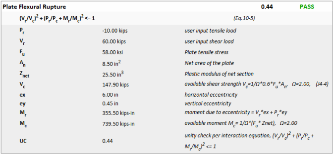
The AISC 13th edition does not specify a formula to use for this situation. Therefore, engineering judgment is required. To ensure consistency between codes, RISAConnection uses the 14th edition equation even if the 13th edition code has been specified.
AISC does not have a true interaction equation for shear tabs subjected to shear in combination with axial compression. However, the commentary associated with AISC 14th edition equation 10-5 suggests that it should be done. Rather than using the square terms similar to equation 10-5, RISAConnection has taken a more conservative stance and directly added the two effects.
When the angle connection is welded and there is axial tension is present in clip angle shear connection, the program automatically places a weld on the bottom of the clip angles as well to provide a weld configuration that can resist the load. However, allowing this type of force introduces the possibility that the connection will fail via angle leg bending and the limit state is introduced as shown below:
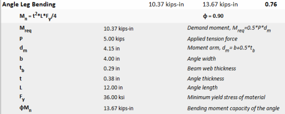
The procedure for checking this limit state is taken from page 15-10 of the AISC Steel Design Manual (equation 15-21). This procedure can also be found in the 3rd edition of Steel Structures: Design and Behavior, by Salmon and Johnson. The assumption is that the legs act as a simply supported beam between weld points subjected to a point load at the mid point of the beam. The capacity would be equal to the plastic bending capacity of an equivalent plate.
When the angle connection is bolted and there is axial tension present in the clip angle shear connection, the program will also check that the angle will not fail due to bending. The procedure for this limit state comes from page 15-10 of the AISC 14th edition Steel Design Manual. The program conservatively uses the 14th edition version of this equation for design per both the 13th and 14th edition design manuals. If you have selected a Canadian design code, the procedure from the Salmon and Johnson textbook will be used.
At this time the program is not considering beam or column bearing per section J1.4(2(i)) or page 14-14, of the AISC 14th edition, respectively.